WT Forums

Home | WT Forums | Hogpedia | Warthog blog | Hosted sites
It is currently 06 Apr 2025, 06:36

All times are UTC [ DST ]


Post new topic Reply to topic  [ 49 posts ]  Go to page 1, 2  Next
Author Message
 Post subject: More tech questions
PostPosted: 16 Jan 2011, 12:37 
Offline
Board Tech
Board Tech
User avatar

Joined: 02 Dec 2010, 14:17
Posts: 44
Location: LKPR/Prague, Czech Republic, Central Europe
Career field: A-10 Enthusiast
After clarifying some APU stuff, I'm back with more technical questions. Now I'm finishing chapter on engines and I'd like to ask about that \"accessory gearbox\". More precisely, how is it driven - high pressure turbine shaft (N2) or LP turbine (fan/N1)? My personal guess is N2, because oil pumps have to be already going when engine core is spinning up - but would starter handle that?
And then, what bugs me most - accessory gearbox is supposed to drive all those hydraulical pumps, generators and so on. But these are inside the hull, scattered around the APU - while engines and their respective accessory gearboxes are on engine pylons, which AFAIK pretty much mechanically isolate them. So how is this solved? Is there some kind of driveshaft, going through the engine pylons, or what?
Also, I've red in that \"A-10 FAQ\" that engine pylons are made in a way they fall off in the case of unmanageable engine fire. But if there's a driveshaft going through the pylons, how could they fall of like that, when driveshafts require hell of a force to break?

Second question would be about the bleed air system. From the schematics in the manual, it looks like there is no valve, isolating APU from the rest of the circuit - but I'd guess that pressure of the air behind engine compressors would be way higher, than pressure generated by the APU - and that this engine-pressurized air would overpressure the APU-pressurized air, get into the APU turbine from behind and destroy it. How is this prevented? Is APU somehow capable of creating air pressure equivalent to the engine one, is there an undocumented APU-isolation valve - or the problem with \"overpressurizing APU turbine\" simply doesn't exit?

Thanks for help and all.


Top
 Profile  
 
 Post subject: Re: More tech questions
PostPosted: 17 Jan 2011, 00:19 
Offline
WT Admin
User avatar

Joined: 16 May 2004, 12:44
Posts: 1517
Location: DMAFB, AZ
Career field: Crew Chief
cover72 wrote:
After clarifying some APU stuff, I'm back with more technical questions. Now I'm finishing chapter on engines and I'd like to ask about that "accessory gearbox". More precisely, how is it driven - high pressure turbine shaft (N2) or LP turbine (fan/N1)? My personal guess is N2, because oil pumps have to be already going when engine core is spinning up - but would starter handle that?

The LPT drives the fan and the HPT drives the compressor. There's a PTO (power take-off) that drives the AGB (accesory gear box), I'm pretty sure it comes from the compressor. Not 100% sure on the second half of that answer.

Quote:
And then, what bugs me most - accessory gearbox is supposed to drive all those hydraulical pumps, generators and so on. But these are inside the hull, scattered around the APU - while engines and their respective accessory gearboxes are on engine pylons, which AFAIK pretty much mechanically isolate them. So how is this solved? Is there some kind of driveshaft, going through the engine pylons, or what?

There are 3 generators and 3 hyd pumps on the whole jet: one of each per engine and one of each on the APU. All of which are mounted directly to the gearbox.

Quote:
Also, I've red in that "A-10 FAQ" that engine pylons are made in a way they fall off in the case of unmanageable engine fire. But if there's a driveshaft going through the pylons, how could they fall of like that, when driveshafts require hell of a force to break?

This is a myth. The engines are not designed to fall off or be jettisoned. The only things inside that run inside the engine pylons are wires and hyd/fuel lines.

Quote:
Second question would be about the bleed air system. From the schematics in the manual, it looks like there is no valve, isolating APU from the rest of the circuit - but I'd guess that pressure of the air behind engine compressors would be way higher, than pressure generated by the APU - and that this engine-pressurized air would overpressure the APU-pressurized air, get into the APU turbine from behind and destroy it. How is this prevented? Is APU somehow capable of creating air pressure equivalent to the engine one, is there an undocumented APU-isolation valve - or the problem with "overpressurizing APU turbine" simply doesn't exit?
Thanks for help and all.

There are lots of valves in the air system, for each engine and the APU. There are both check valves and shutoff valves. In any case though, the air pressure is not high pressure, it is high volume.


Top
 Profile  
 
 Post subject:
PostPosted: 17 Jan 2011, 09:33 
Offline
Board Tech
Board Tech
User avatar

Joined: 02 Dec 2010, 14:17
Posts: 44
Location: LKPR/Prague, Czech Republic, Central Europe
Career field: A-10 Enthusiast
Thanks very much.
So you are basically saying that generator AND hyd pump (green on image 1) AND starter are all located in that tiny, engine-mounted AGB (green on image 2)?
And that hydraulic reservoirs are not exactly next to the pumps, as it looks from the schematics, but inside the hull (green on image 3)?
Image

Because it was the hydraulic system schematic what made me believe the hydraulic pumps were inside the hull - the \"3D\" view might be a little bit confusing as for the physical location of the components.
Anyway, if I get it right, there is no essential difference between, say, Hog's AGB and Hornet's AMAD (Airframe Mounted Accessory Drive), as they're both powered mechanically by engine and contain starter as well as pump and generator; is that correct?

As for the APU - so there actually is a valve which isolates APU bleed air after the starters spins up engine turbines and these take over the job of supplying the bleed air system, only it isn't shown on the \"bleed air schematic\"?


Top
 Profile  
 
 Post subject:
PostPosted: 18 Jan 2011, 06:45 
Offline
WT Admin
User avatar

Joined: 16 May 2004, 12:44
Posts: 1517
Location: DMAFB, AZ
Career field: Crew Chief
Quote:
So you are basically saying that generator AND hyd pump (green on image 1) AND starter are all located in that tiny, engine-mounted AGB (green on image 2)?

The part being pointed to in picture 1 is the hyd pump. It is mounted to the AGB, which is invisible in that picture. The kind of flat/curved thing just above the hyd pump is the cooler.

In picture 2, the left-most part of the green highlighting is the AGB. The part in the middle is the fuel control and the aft part is the fuel filter

Quote:
And that hydraulic reservoirs are not exactly next to the pumps, as it looks from the schematics, but inside the hull (green on image 3)?

Correct. The left sys res is the front one, the rt sys res is the aft one.

Quote:
Because it was the hydraulic system schematic what made me believe the hydraulic pumps were inside the hull - the \"3D\" view might be a little bit confusing as for the physical location of the components.
Anyway, if I get it right, there is no essential difference between, say, Hog's AGB and Hornet's AMAD (Airframe Mounted Accessory Drive), as they're both powered mechanically by engine and contain starter as well as pump and generator; is that correct?

You got it. The AGB on the A-10 contains (from right to left) the hyd pump, starter, generator, oil pump and fuel control

Quote:
As for the APU - so there actually is a valve which isolates APU bleed air after the starters spins up engine turbines and these take over the job of supplying the bleed air system, only it isn't shown on the \"bleed air schematic\"?

I've never looked at a bleed air schematic, but it has to be in the T.O.'s... The valves, several thoughout the system, definitely exist in real life.

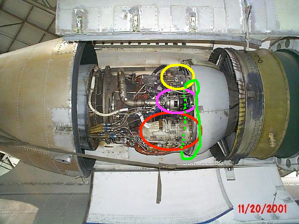
This might help...
Image
This is the #2 engine, the engines are identical left and right. The only difference is the mount locations, which can be swapped (you cannot order a \"left engine\" or \"right engine\" just \"an engine\" and where you install the mount is what makes it a left or right.
The yellow is the hyd pump (at 2:00 is the cooler)
The purple is the starter
The red is the generator
The green is the AGB


Top
 Profile  
 
 Post subject:
PostPosted: 18 Jan 2011, 07:53 
Offline
Board Tech
Board Tech
User avatar

Joined: 02 Dec 2010, 14:17
Posts: 44
Location: LKPR/Prague, Czech Republic, Central Europe
Career field: A-10 Enthusiast
Aha, I finally get it. Thanks a lot.
Would you mind if I used that picture of yours in my book?


Top
 Profile  
 
 Post subject:
PostPosted: 18 Jan 2011, 08:17 
Offline
WT Admin
User avatar

Joined: 16 May 2004, 12:44
Posts: 1517
Location: DMAFB, AZ
Career field: Crew Chief
I didn't take that one, if that matters. I have some other much better ones if you want. If you want I can email them to you.


Top
 Profile  
 
 Post subject:
PostPosted: 19 Jan 2011, 09:26 
Offline
WT Admin
User avatar

Joined: 16 May 2004, 12:44
Posts: 1517
Location: DMAFB, AZ
Career field: Crew Chief
I emailed you a few pics. Feel free do do what you want with them.


Top
 Profile  
 
 Post subject:
PostPosted: 23 Feb 2011, 11:36 
Offline
Board Tech
Board Tech
User avatar

Joined: 02 Dec 2010, 14:17
Posts: 44
Location: LKPR/Prague, Czech Republic, Central Europe
Career field: A-10 Enthusiast
Ok, so I got through the \"systems\" chapter and now, I'm on to \"airframe\". And as I know virtually nothing about airframes and so on, please bear with me. I'll either edit this post or add more posts as more questions emerge. So far,
1) is Hog's angle of sweep 0, or some non-zero number?
2) as far as I understand the function of manual FCS, ailerons are controlled indirectly, via those little control surfaces - instead of directly via aileron actuators. Why is that? I mean, pilot has to move the whole ailerons after all, or not? So the aerodynamical forces would be the same. So why this indirect approach?
3) deceleron function. Do I understand it correct that in the case of ABK deployment, the surface splits on the lower and higher half but still move as a whole to provide aileron function?
4) what for is \"lift transducer\" for in the A-10? Some sources claim it controls leading edge slats, but those should be more like function-of-AoA-controlled, shouldn't they?
5) I expect no one would know or tell, but still - wouldn't there be some numbers on Hog's maximal stable and instantaneous AoA?
6) Little data inconsistency on flaps. Some sources claim they are \"2 segment, 3 position\", while others say that flaps only have two positions, that being \"full up\" and \"full down\". Apart from that, would would be the flap angles - I've red \"7deg\", but that seems awfully low to me...
7) What is the wing camber between landing gear condoles and the wing tip?


Top
 Profile  
 
 Post subject:
PostPosted: 23 Feb 2011, 13:56 
Offline
WT Game Warden
User avatar

Joined: 17 Jun 2002, 09:37
Posts: 1630
Location: Warner Robins, Ga
I'll do my best to answer (in bold). I know someone will correct me if I'm wrong.

cover72 wrote:
Ok, so I got through the "systems" chapter and now, I'm on to "airframe". And as I know virtually nothing about airframes and so on, please bear with me. I'll either edit this post or add more posts as more questions emerge. So far,
1) is Hog's angle of sweep 0, or some non-zero number?
Don't know this one
2) as far as I understand the function of manual FCS, ailerons are controlled indirectly, via those little control surfaces - instead of directly via aileron actuators. Why is that? I mean, pilot has to move the whole ailerons after all, or not? So the aerodynamical forces would be the same. So why this indirect approach?
The ailerons have their own actuator, the trim tabs only control the aileron movement in manual reversion
3) deceleron function. Do I understand it correct that in the case of ABK deployment, the surface splits on the lower and higher half but still move as a whole to provide aileron function?
Exactly
4) what for is "lift transducer" for in the A-10? Some sources claim it controls leading edge slats, but those should be more like function-of-AoA-controlled, shouldn't they?
It is for the slats in front of both engines, controls them moving up and down
5) I expect no one would know or tell, but still - wouldn't there be some numbers on Hog's maximal stable and instantaneous AoA?
6) Little data inconsistency on flaps. Some sources claim they are "2 segment, 3 position", while others say that flaps only have two positions, that being "full up" and "full down". Apart from that, would would be the flap angles - I've red "7deg", but that seems awfully low to me...
Flaps have three positions, full up, 7 degree, and full down
7) What is the wing camber between landing gear condoles and the wing tip?
Don't know this one either

_________________
Image


Top
 Profile  
 
 Post subject:
PostPosted: 23 Feb 2011, 19:10 
Offline
Hog Driver

Joined: 27 Oct 2002, 00:46
Posts: 952
Location: NAS Norfolk VA
cover72 wrote:
Ok, so I got through the "systems" chapter and now, I'm on to "airframe". And as I know virtually nothing about airframes and so on, please bear with me. I'll either edit this post or add more posts as more questions emerge. So far,
1) is Hog's angle of sweep 0, or some non-zero number?
2) as far as I understand the function of manual FCS, ailerons are controlled indirectly, via those little control surfaces - instead of directly via aileron actuators. Why is that? I mean, pilot has to move the whole ailerons after all, or not? So the aerodynamical forces would be the same. So why this indirect approach?
3) deceleron function. Do I understand it correct that in the case of ABK deployment, the surface splits on the lower and higher half but still move as a whole to provide aileron function?
4) what for is "lift transducer" for in the A-10? Some sources claim it controls leading edge slats, but those should be more like function-of-AoA-controlled, shouldn't they?
5) I expect no one would know or tell, but still - wouldn't there be some numbers on Hog's maximal stable and instantaneous AoA?
6) Little data inconsistency on flaps. Some sources claim they are "2 segment, 3 position", while others say that flaps only have two positions, that being "full up" and "full down". Apart from that, would would be the flap angles - I've red "7deg", but that seems awfully low to me...
7) What is the wing camber between landing gear condoles and the wing tip?


1. Not sure, but I don't think it has any sweep.
2. It allows the pilot easier control without heavy airloads to move the ailerons. The trim tabs are used to "fly" the ailerons in manual reversion. Sloppy, but effective. (cheap)
3. Yes.
4. The lift transducer provides the stall warning/peak performance tone as well as the schedules the slats and engine ignition in high AoA situations. Crude, but effective. (cheap)
5. L/D max is 17.5 units, max range is 15.4 units and stall is about 24.5 units. Pulled these from way back in my memory, so they may be off by .1 or so.
6. Flaps can be set to zero (Up), 7 (MVR) or 20 degrees (Full).
7. Can't help you here...

Coach


Top
 Profile  
 
 Post subject:
PostPosted: 23 Feb 2011, 19:56 
Offline
Board Tech
Board Tech
User avatar

Joined: 02 Dec 2010, 14:17
Posts: 44
Location: LKPR/Prague, Czech Republic, Central Europe
Career field: A-10 Enthusiast
Thanks. Only I didn't quite get the descriptions of AoA values - what means that \"max range\" for 15.4? I would read it as \"optimal AoA for long range flights\", but 15.4 would be way too much for that... Same confusion about \"L/D\" abbreviation. Again, sorry for my incompetence in this field :oops:


Top
 Profile  
 
 Post subject:
PostPosted: 23 Feb 2011, 20:55 
Offline
Hog Driver

Joined: 27 Oct 2002, 00:46
Posts: 952
Location: NAS Norfolk VA
cover72 wrote:
Thanks. Only I didn't quite get the descriptions of AoA values - what means that "max range" for 15.4? I would read it as "optimal AoA for long range flights", but 15.4 would be way too much for that... Same confusion about "L/D" abbreviation. Again, sorry for my incompetence in this field :oops:


Units are arbitrary, not necessarily transferrable between different aircraft.

L/D Max: maximum endurance AoA. Optimum AoA for longest time aloft.
Max Range is the optimum AoA for long range flights, as you state.

Coach


Top
 Profile  
 
 Post subject:
PostPosted: 02 Mar 2011, 14:03 
Offline
Board Tech
Board Tech
User avatar

Joined: 02 Dec 2010, 14:17
Posts: 44
Location: LKPR/Prague, Czech Republic, Central Europe
Career field: A-10 Enthusiast
About that 2) - maybe I misunderstood the whole concept of aileron operation.
As I got it from the manual, I thought that aileron trim was purely hydraulic based - trim would affect the hydraulic actuators in a way that they would \"feel\" sustained \"fake pilot input\"; and that with full manual/backup FCS, pilot would still have to move the whole ailerons (because there is no longer any hyd pressure left to move them), only he does so via \"mechanical workaround\" - that being literally workaround.

But if I get this straight, you are basically telling me pilot does not move the ailerons, but trim tabs? And that those trim tabs somehow get ailerons to move? (If yes, then how on the earth? Aerodynamical forces would still be against such movement...)
And that would indicate that \"aileron trim mechanism\" isn't based on \"fake inputs into HYD actuator\", but on trim-flight-control-surfaces instead? Like this?
Image


Top
 Profile  
 
 Post subject:
PostPosted: 02 Mar 2011, 16:13 
Offline
Ex-Crewdog
User avatar

Joined: 18 Apr 2002, 19:39
Posts: 802
Location: Region 10
Career field: Crew Chief
Normal trim is electro-hydraulically controlled, IIRC. The trim tabs (the green portion in your illustration) are used during manual reversion to move the deceleron via air movement changes.

As far as the red area in your illustration, I have no f'ing clue what that is. In fact, I don't think I ever saw anything in that area.

_________________
3 Branches down... 2 to go!
Put on your tinfoil hats, the black choppers are coming, and I'm calling them in.
Former DCC OA-10A T/N 80-278


Top
 Profile  
 
 Post subject:
PostPosted: 02 Mar 2011, 16:50 
Offline
WT Admin
User avatar

Joined: 16 May 2004, 12:44
Posts: 1517
Location: DMAFB, AZ
Career field: Crew Chief
Theres nothing in the red area. Also, if it matters, the trim tab (also referred to as the servo tab on the aileron) is attached to the top board. There is a cutout on the bottom board for it to move when the deceleron is closed.


Top
 Profile  
 
 Post subject:
PostPosted: 03 Mar 2011, 04:27 
Offline
Hog Driver

Joined: 27 Oct 2002, 00:46
Posts: 952
Location: NAS Norfolk VA
In man reversion, the pilot does not move the ailerons. That's what I'm telling you.


Top
 Profile  
 
 Post subject:
PostPosted: 03 Mar 2011, 14:45 
Offline
Board Tech
Board Tech
User avatar

Joined: 02 Dec 2010, 14:17
Posts: 44
Location: LKPR/Prague, Czech Republic, Central Europe
Career field: A-10 Enthusiast
Aha, I finally got it. Thanks a lot.
So in the manual reversion, pilot controls the roll via trim tabs. How much slower/harder would it be to roll the plane via these, then? Also, I guess that roll sensitivity on trim tabs decreases alongside with airspeed (and airflow), so landings and so on could be rather tricky?


Top
 Profile  
 
 Post subject:
PostPosted: 04 Mar 2011, 01:07 
Offline
Hog Driver

Joined: 27 Oct 2002, 00:46
Posts: 952
Location: NAS Norfolk VA
Experience shows you have less than a 50-50 chance of a successful landing (one in which the aircraft flies again) in man reversion when everything is going well. We've lost several great Americans along the way.

In training use, there is a fairly restrictive airspeed, bank and climb/dive angle range when in man reversion due to excessive control forces at high speed and lack of control response at slower speeds. If the flaps are down, you may not be able to control the aircraft.

The system is designed to get you out of enemy territory so you can bailout.

Coach


Top
 Profile  
 
 Post subject:
PostPosted: 04 Mar 2011, 07:33 
Offline
Board Tech
Board Tech
User avatar

Joined: 02 Dec 2010, 14:17
Posts: 44
Location: LKPR/Prague, Czech Republic, Central Europe
Career field: A-10 Enthusiast
I see. Thanks very much for explaining all of this and bearing with me.


Top
 Profile  
 
 Post subject:
PostPosted: 23 Mar 2011, 14:06 
Offline
Board Tech
Board Tech
User avatar

Joined: 02 Dec 2010, 14:17
Posts: 44
Location: LKPR/Prague, Czech Republic, Central Europe
Career field: A-10 Enthusiast
Hi, I'm back, this time with landing gear questions.
1) wouldn't somebody know some tires parameters? Manufacturer (suppose it isn't Michelin Air, is it?), inflation pressure, number of grooves, size/PR...
2) FM reads that auxiliary gear extension mechanism also opens valve which \"depressurizes left HYD SYS reservoir and thereby minimizes the back pressure against which the gear must fall\". Now, where does the released hydraulic fluid go? Is it dumped over board? Or does it return from gear hyd circuit to the main L HYD circuit (in that cause, how? LHYD has it's own pressure, so pressing it back there would require pump..)?
3) The anti-skid system. Is it something smart as ABS, or does it just completely release brakes if it detects zero wheel spin?
4) Do i get it right from the picture 1-26 that the normal landing gear handle directly controls the landing gear extend/retract hydraulic valve via an electro-magnet?
5) as for the nosewheel steering, what would be the deflection angles?
6) scheme 2-12 shows \"Ground clearance\". But I suppose that shock struts retract/extend as a function of Hog's current weight/payload, so for what weight would the front wheel clearance be that cited 5'0''? And for the same weight, what would be the ground clearance of the lowest point of Hog, that being the main LG pods?
Thanks in advance.


Top
 Profile  
 
 Post subject:
PostPosted: 23 Mar 2011, 16:40 
Offline
WT Admin
User avatar

Joined: 16 May 2004, 12:44
Posts: 1517
Location: DMAFB, AZ
Career field: Crew Chief
cover72 wrote:
Hi, I'm back, this time with landing gear questions.
1) wouldn't somebody know some tires parameters? Manufacturer (suppose it isn't Michelin Air, is it?), inflation pressure, number of grooves, size/PR...

Michelin Air
nose pressure 140+/-5
nose size 24x7.7, 14 ply
main pressure 185+/-5
main size 36x11, 22 ply, 3 or 4 groove, can be either

Quote:
2) FM reads that auxiliary gear extension mechanism also opens valve which "depressurizes left HYD SYS reservoir and thereby minimizes the back pressure against which the gear must fall". Now, where does the released hydraulic fluid go? Is it dumped over board? Or does it return from gear hyd circuit to the main L HYD circuit (in that cause, how? LHYD has it's own pressure, so pressing it back there would require pump..)?
It goes back through the return of the left system. How? Check valves I guess, it's pretty hard to understand how things like certain valves or the supply module work, just so long as you know how they are supposed to work you can do your job.

Quote:
3) The anti-skid system. Is it something smart as ABS, or does it just completely release brakes if it detects zero wheel spin?
When the wheels are decelerating faster than 25' per second, the anti-skid control valve dumps the brake pressure and reapplies it at a pressure just under when caused the skid. Just like ABS on a car.

Quote:
4) Do i get it right from the picture 1-26 that the normal landing gear handle directly controls the landing gear extend/retract hydraulic valve via an electro-magnet?

Picture 1-26 of what manual? The landing gear control panel is wiring only. The wires go to valves and solenoids and tell them to do their thing. The Auxiliary extension handle is cable operated.

Quote:
5) as for the nosewheel steering, what would be the deflection angles?

69° left and 72° right

Quote:
6) scheme 2-12 shows "Ground clearance". But I suppose that shock struts retract/extend as a function of Hog's current weight/payload, so for what weight would the front wheel clearance be that cited 5'0''? And for the same weight, what would be the ground clearance of the lowest point of Hog, that being the main LG pods?
Thanks in advance.

Clearance? Do you mean 5" of strut extension? If the nose is at 5", the corresponding weight for it to be correctly serviced is ~40,000lbs. The mains would be at ~3" at that weight.
At 40,000lbs, the bottom of the MLG pods would be around 4'. (I'm eyeballing this at home with references to where it would be compared to my body. Definitely not 5' though.)


Top
 Profile  
 
 Post subject:
PostPosted: 24 Mar 2011, 17:19 
Offline
Board Tech
Board Tech
User avatar

Joined: 02 Dec 2010, 14:17
Posts: 44
Location: LKPR/Prague, Czech Republic, Central Europe
Career field: A-10 Enthusiast
Thanks very much.
The only manual I have is 1A-10A-1, where the given picture/schematics look like this:
Image
Arrow points on what looks like a soleloid-functioning-like-electromagnet, directly mechanically linked to the main landing gear valve. But from what you say, I suppose was wrong and the landing gear lever is not directly connected to that, is it?

About that clearance thing - well, the picture says \"clearance\" and cites 5':

Image

And one more question emerged: due to fact the main LG rims are supposed to work as a backup for blown tire, what material are they from - aluminum, or steel?


Top
 Profile  
 
 Post subject:
PostPosted: 24 Mar 2011, 19:05 
Offline
User avatar

Joined: 17 Jun 2002, 10:29
Posts: 5935
Location: S of St Louis but in IL
Don't forget those pesky antennae when calculating clearance. :wink: [shock]

_________________
\"Those who hammer their guns into plows
will plow for those who do not.\"
- Thomas Jefferson


Top
 Profile  
 
 Post subject:
PostPosted: 24 Mar 2011, 19:35 
Offline
WT Admin
User avatar

Joined: 16 May 2004, 12:44
Posts: 1517
Location: DMAFB, AZ
Career field: Crew Chief
Correct, the LDG contral panel/handle is not directly mechanically connected to the landing gear control valve. The wires from the control panel go to the a control box, relays, switches, the LDG control valve and probably a few other parts.

Hmm, the bottom of the gun scoop 5' off the ground is probably a bit higher than it would be on a fully loaded properly serviced jet. But not significantly. I'm talking 6\" or less.


Top
 Profile  
 
 Post subject:
PostPosted: 25 Mar 2011, 07:25 
Offline
WT Admin
User avatar

Joined: 16 May 2004, 12:44
Posts: 1517
Location: DMAFB, AZ
Career field: Crew Chief
I measured the ground clearance tonight at work...
Normal config the the gun scoop is 5', bottom of the gear pod is 4' and the vertical stab is 4' 6\".

99.9% sure the wheels are aluminum, or some type of alloy. They're heavy, but not heavy enough to be made of steel.


Top
 Profile  
 
Display posts from previous:  Sort by  
Post new topic Reply to topic  [ 49 posts ]  Go to page 1, 2  Next

All times are UTC [ DST ]


Who is online

Users browsing this forum: No registered users and 4 guests


You cannot post new topics in this forum
You cannot reply to topics in this forum
You cannot edit your posts in this forum
You cannot delete your posts in this forum
You cannot post attachments in this forum

Search for:
Jump to:  
Powered by phpBB® Forum Software © phpBB Group